
STANDARD CONSTRUCTION
• T316 SS wetted, T304 SS non-wetted
• 5/8″ diameter smooth end fittings— fits 5/8″ Stuffingbox
• Armor: Slotted both front and back for see-thru visibility
• Glass: 5/8″ O.D. Plain (clear)
• O-Ring Seals, Size -208, Viton (400° F max)
• Outer “ring” bumpers located behind cross tie, between open windows, keep glass centered inside body. Bumpers are required to prevent bending of glass caused by end loads, and to maintain pressure rating. Ring bumpers are always provided by the factory.
• Pressure vs Temperature Ratings
- – Gage NOT rated for steam because of high corrosion rates in hot water
- – Pressure ratings are valid only when outer ring bumpers are maintained.
- 315 psi @ 150° F
- 305 psi @ 200° F
- 300 psi @ 250° F (non Steam)
- 290 psi @ 300° F (non Steam)
- 280 psi @ 350° F (non Steam)
- 275 psi @ 400° F (non Steam)
- 270 psi @ 425° F (non Steam)… AFLAS required above 400° F
OPTIONS
• Red Line Glass for enhanced viewing of clear liquids
• Lexan Snap-On Guard, provides extra protection
• O-Ring seal : TFE, BUNA-N, EPDM, AFLAS, etc.
• 1/2″ M-NPT End Fittings, also 1/4″ F-NPT & 1/2″ F-NPT
• Extra Long Smooth End Fittings for longer C-C Retrofits
DESIGN
• Consult factory for low process temperature applications
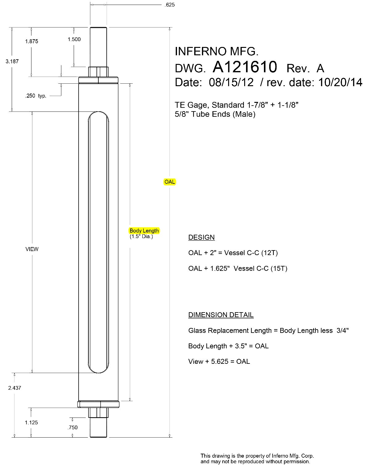
DIMENSIONS—MODEL “TE” with Tubular Glass Gage Valves
- Model 12T or FT-TUB Valves (steel or SS): OAL = C-C less 2″… Visible Glass Range = C-C less 7.625″
- Model 15T Valves (steel or SS): OAL = C-C less 1.625″… Visible Glass Length = C-C less 7.25″
- Conbraco (brass) 20-250 / 20-251 Valves:: OAL = C-C less 1.25″… Visible Glass Length = C-C less 6.875″
REPLACEMENT GLASS LENGTH = Body OAL less 0.75″…. note Body OAL measured without jam nuts
HOW TO ORDER
1- Specify gage valve model
2- Specify vessel C-C
3- Specify options if any
4- To retrofit existing bare glass installations… the OAL of the replacement Model TE is the same length as the original bare glass
INSTALLATION
1-Install gage valves in vessel- be sure that Lower gage valve is at bottom. Upper valve has deep well, Lower valve has glass seating shelf
2- install with short End Fitting at bottom and longer End Fitting at top
MAINTENANCE
WARNING: When replacing glass tube be sure to transfer the outer ring bumper to the new glass and position ring behind the cross tie between windows… One ring bumper is required at each cross tie to prevent buckling (bending caused by pressure loading of glass ends).
CAUTION
Use Model TE Armored Tubular Gages with gage valves (gage cocks) with automatic safety ball checks to minimize loss of fluid in case of glass breakage. Gage valves must be in good working order and operators trained in useage. Are Your Ball Checks Workings?
Armored reflex and transparent type level gages with more protection are available for high risk applications.
revised 11-23-15